3DPrintworx Appointed Voxeldance Additive Distributor
15% discount for all sales during TCT 3Sixty 2025
15% discount for all sales during TCT 3Sixty 2025

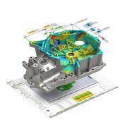
Polyworks Inspector is an industrial 3D metrology software with a strong focus on portable 3D scanning and probing applications.
A comprehensive inspection solution ideal for individual part reporting or full assembly reports, Polyworks inspector has many tools for industry alignment standards, freeform surface inspection and GD&T analysis.

The inspection of a component always begins with the alignment of a datum reference system defined either on the CAD model or 2D drawing. This alignment is probably the single most important part of quality control inspection as ‘poor’ or incorrect alignments can mean incorrect inspection and thus not giving engineers the correct feedback they need to make decisions. Polyworks has class leading alignment tools to align from:
.
The extraction of measured dimensions from either point cloud or polygonal models is at the core of the Inspector module. Define exact parameters for the accurate extraction of surface, boundary, and cross-sections measurements. Once defined these measurements can be saved into part inspection sequences to rapidly measure multiple components and produce consistent reports.
Polworks Inspector can measure:
.


Polyworks reporting module has advanced technology that enables graphics and inspection tables to be defined in a particular layout and format, defined by the end-user, to create reports bespoke to each company and exactly as they require the ‘look and feel’. This template is accurately repeated and updated for multiple part inspection requiring no user intervention by the operator.
Polworks Viewer offers a unique way to share inspection projects companywide without the need for additional software licences.

Scan – Process – Edit- Surface
SCAN IT, MESH IT, SURFACE IT. IN MINUTES
Geomagic Wrap is the perfect software solution to convert scan data from digitisers/3D scanners into usable 3D mesh models and surface models, for use in downstream 3D processes such as reverse engineering, 3d printing and quality control inspection.
Geomagic Wrap enables users to transform point cloud data, probe data and imported 3D formats into 3D polygon meshes for use in manufacturing, analysis, design, entertainment, archeology and analysis.
Powerful point cloud processing tools quickly and easily clean large RAW point clouds before converting them into triangulated 3D mesh models. Extensive toolsets exist to analyse and repair triangulated surfaces to create clean watertight topology end exportable in neutral formats such as STL, OBJ, VRML and IGES.


Geomagic Wrap has automated functions to create rapid Nurbs surfaces for those applications that require CAD surfaces such as IGES or STEP. This surfacing technique is particularly suited to organic 3D models such as archeology, buildings, art and sculpture.

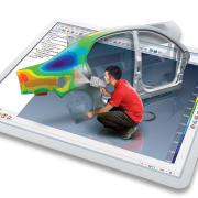
Geomagic Control X is a comprehensive metrology software, focusing on the process of 3D scan to CAD comparison.
A simple, intuitive workflow enables managers to rapidly understand and provide information rich reporting, helping with quality gains in the manufacturing workflow.

Quickly create first article inspection reports with CAD based dimensioning tools that extract the relevant measurements from multiple components, every time the 3d scan data is replaced. Native CAD import of 3D models with GD&T definitions contained within the model at no extra cost.
Improve the ability to report issues across mulitple inspections of the same component with the ability to analyise history trends over time and from multiple scanning/probing devices. Undesrtand potential assembly issues with the ability to create alignments that match fit and assemblyof components.


New powerful reporting tools creating graphically-rich content enables managers to quickly understand and learn quality concerns on component parts. Custom viewpoint control empowers the user to create reports that closely follow a traditional PDF or 2D paper drawing. Export your reports in a number of configurations and formats giving full flexibility to create a comprehensive management reporting system.
Nist-PTB certified results give you the confidence in your inspection process that has accountability and traceability.

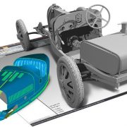
Geomagic Design X, the industry’s most comprehensive reverse engineering software, combines history-based CAD with 3D scan data processing so you can create feature-based, editable solid models compatible with your existing CAD software.
Live transfer of reverse engineered models into Solidworks, PTC Creo, Siemens NX and Autodesk Inventor, means reverse engineered models can be seamlessly transferred into your native CAD system as if they had been designed from scratch with full feature based parametric history trees.


3D Scan Data.

Region Segment automatically segments the model into geometrical features such as planes, cylinders, cone etc.

2D Sections can be dimensioned to re-model as measured or to adjust to ‘original design intent’.

Automatically extrude, revolve, sweep, loft functions to reverse engineer your model back to CAD.

Parametric Solid Model with full history tree ready for Solidworks, PTC Creo, Siemens NX and Autodesk Inventor.
.

Analyser to check the accuracy of 3d reverse engineered model to original scan data.