Polyworks Modeler
IMAlign Module
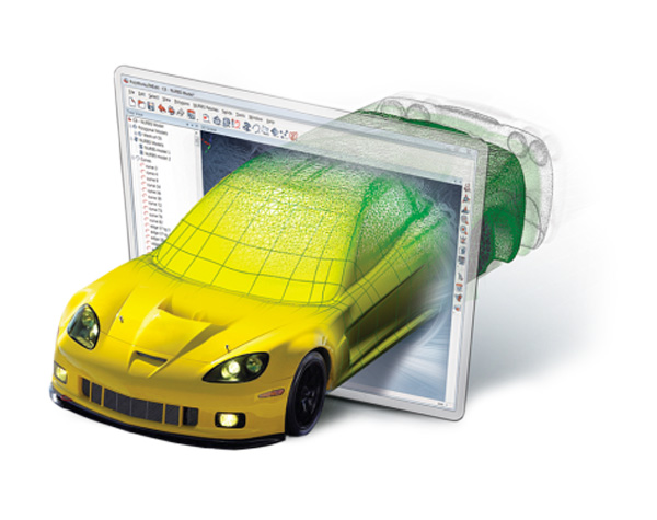
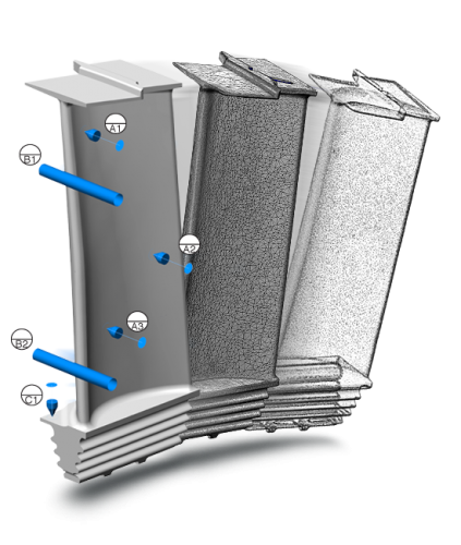
3D scan data is ‘real time’ interpolated to display a rendered surface allowing the user to quickly visualise what areas of a component have already been scanned. Furthermore powerful tools exist to move the 3d scanner into different locations around the part and then ‘align’ the datasets. Grouping of particular datasets and algorithms to fit these together allows the user to view statistics on the accuracy and fit of data, giving complete control and re-assurance as to the validity of datasets.
IMEdit
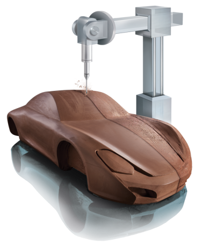
Powerful module to manipulate and edit 3d polygonal meshes by hole filling and optimising triangle structure in order that the models can be used directly for 3d printing, direct milling, or aerodynamic simulation software.
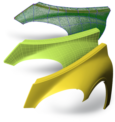
Polyworks has a novel way to create accurate NURBS surfaces on 3d mesh models, curves are first of laid down on top of the scan following the key profile shapes of the object. The Curves are then intersected to produce 4 or N sided surface patches and combined to produce a finished NURBS surface exportable as IGES or STEP.
Sector Suitability
Polyworks Inspector
Align
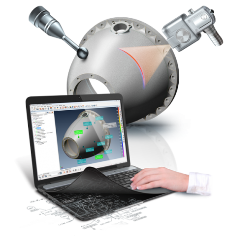
The inspection of a component always begins with the alignment of a datum reference system defined either on the CAD model or 2D drawing. This alignment is probably the single most important part of quality control inspection as ‘poor’ or incorrect alignments can mean incorrect inspection and thus not giving engineers the correct feedback they need to make decisions. Polyworks has class leading alignment tools to align from:
- Surfaces or cross-sections allowing completely freeform fit or constrained in a particular axis or rotation.
- GD&T datum reference based alignments
- RPS – Reference Point System alignments
- Virtual Gauge alignments – Gap and Flush, caliper and air foil.
.
Measure
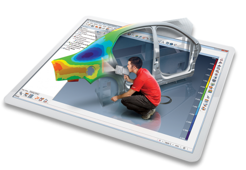
The extraction of measured dimensions from either point cloud or polygonal models is at the core of the Inspector module. Define exact parameters for the accurate extraction of surface, boundary, and cross-sections measurements. Once defined these measurements can be saved into part inspection sequences to rapidly measure multiple components and produce consistent reports.
Polworks Inspector can measure:
- Surface, boundaries and cross-sections to nominal data
- GD&T dimensions and datums
- Real-time assembly guidance
- Advanced dimensions – Flush and Gap, Profile Radius, Airfoil measurement and thickness
.
Report
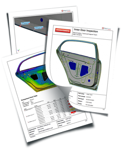
Polyworks reporting module has advanced technology that enables graphics and inspection tables to be defined in a particular layout and format, defined by the end-user, to create reports bespoke to each company and exactly as they require the ‘look and feel’. This template is accurately repeated and updated for multiple part inspection requiring no user intervention by the operator.
Polworks Viewer offers a unique way to share inspection projects companywide without the need for additional software licences.

